DIY switch replacement on MPC 2500

I have had a problem for quite some time now, and I’ve finally got around to fixing it. You see those six buttons below the screen? They work TERRIBLY and have since I purchased this machine used in 2016 or so. They either don’t respond at all, or over-respond with many multiple unintended clicks. In a studio setting, it causes multiple events to be added and deleted which can range from annoying and time-wasting to disastrous. And when you go to save projects, it’s never clear until you’ve pressed multiple times that it has actually responded. More importantly in a live setting, those buttons control the timing of drum rolls, and it makes switching between 16th or 32nd notes virtually impossible, something that I used to frequently employ as a live technique. Now that I’m playing some live gigs, the handicap is too great and I have to attempt a fix.
Preparation
As it turns out, the switches below those buttons were only rated for 10 thousand clicks or so and it showed on these high-use buttons. So I did some research and found that this was a fairly common occurrence and that people were replacing them with switches rated for 1 MILLION clicks, which will surely outlast the machine itself and probably me. But, I am not good at soldering and I was not looking forward to doing the repair myself, but after finally ordering a soldering station, some new switches, and crucially, a solder pump, I was ready to go.
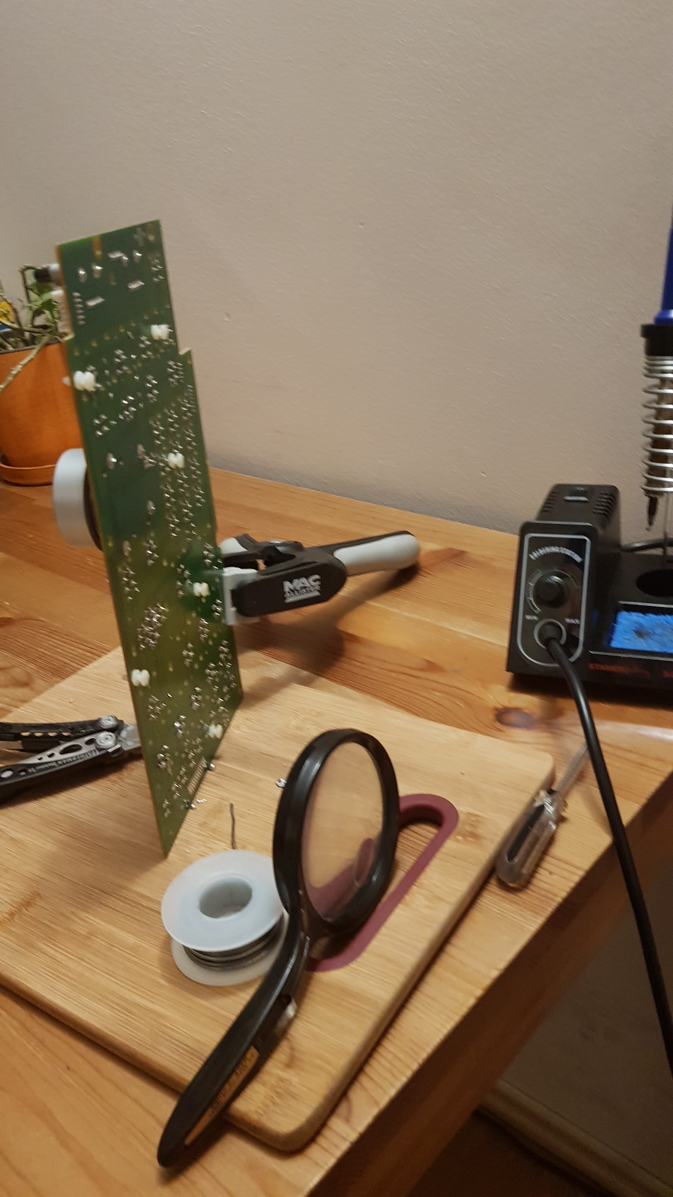
testing on an old board
First though, I felt like I needed to practice doing this repair, and luckily I had an old board with the exact switches that I could practice on. I had tried before to remove these but they proved more difficult than I thought because a little solder would be left on there and I couldn’t pull them off with pliers. That’s when I realized I needed a solder pump, and this helped remove the excess bits so that I could get a little screwdriver under there to carefully pry them out. I tried a few different temperatures on the soldering iron to see what was the minimum I needed to get good melt without overheating the plastic board and I also rigged this magnifying glass so that I could see up close what I was doing. After I had finished practicing adding and removing solder to the pins, careful to avoid overheating the tiny diode next to them or creating a short between them, I was ready to give it a go on the real machine. I didn’t know what awaited me when I went to access these switches, if I had to remove the screen or whatever, but now it was time to press forward.
Repair
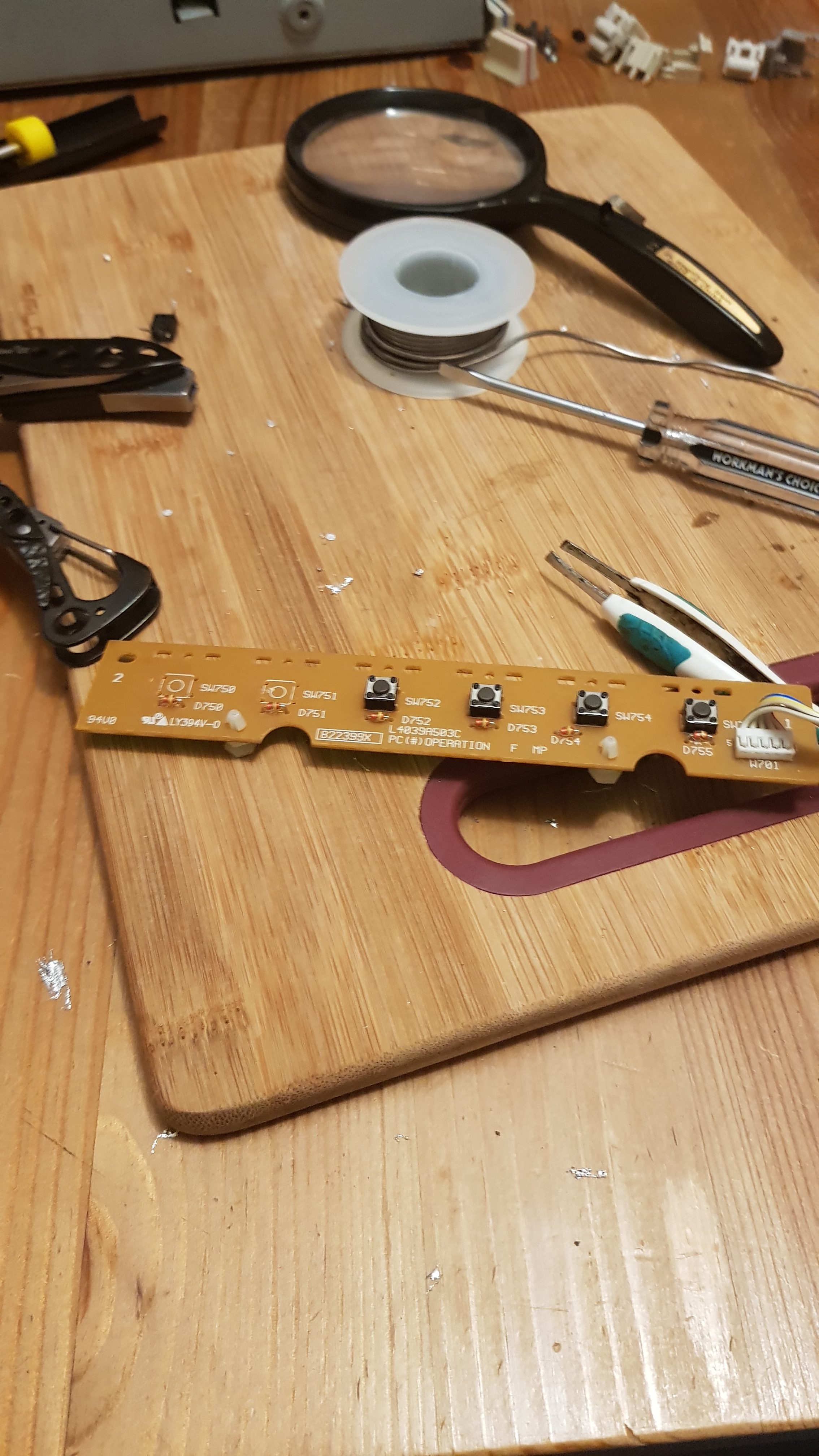
almost ready
Once I got it opened up, I was in for a pleasant surprise…the only things connecting the board to the switches were two screws and a small connector cable. Fantastic! No need to completely disassemble the machine to get at these switches. I think for someone who has more experience with soldering, this would be an easier process than it was for me, but I didn’t rush and went about removing the switches. Once you’ve got as much solder off as you can, try to bend the pins straight and if you can,

switch graveyard
apply heat to one pin while slightly pulling on the switch to loosen that leg. Luckily I did not care about saving these old crappy switches so my main concern was just not damaging the board. I lost a leg or two removing these but for the most part I was able to free them with a small flat screwdriver more or less in one piece. Once they were free, and I
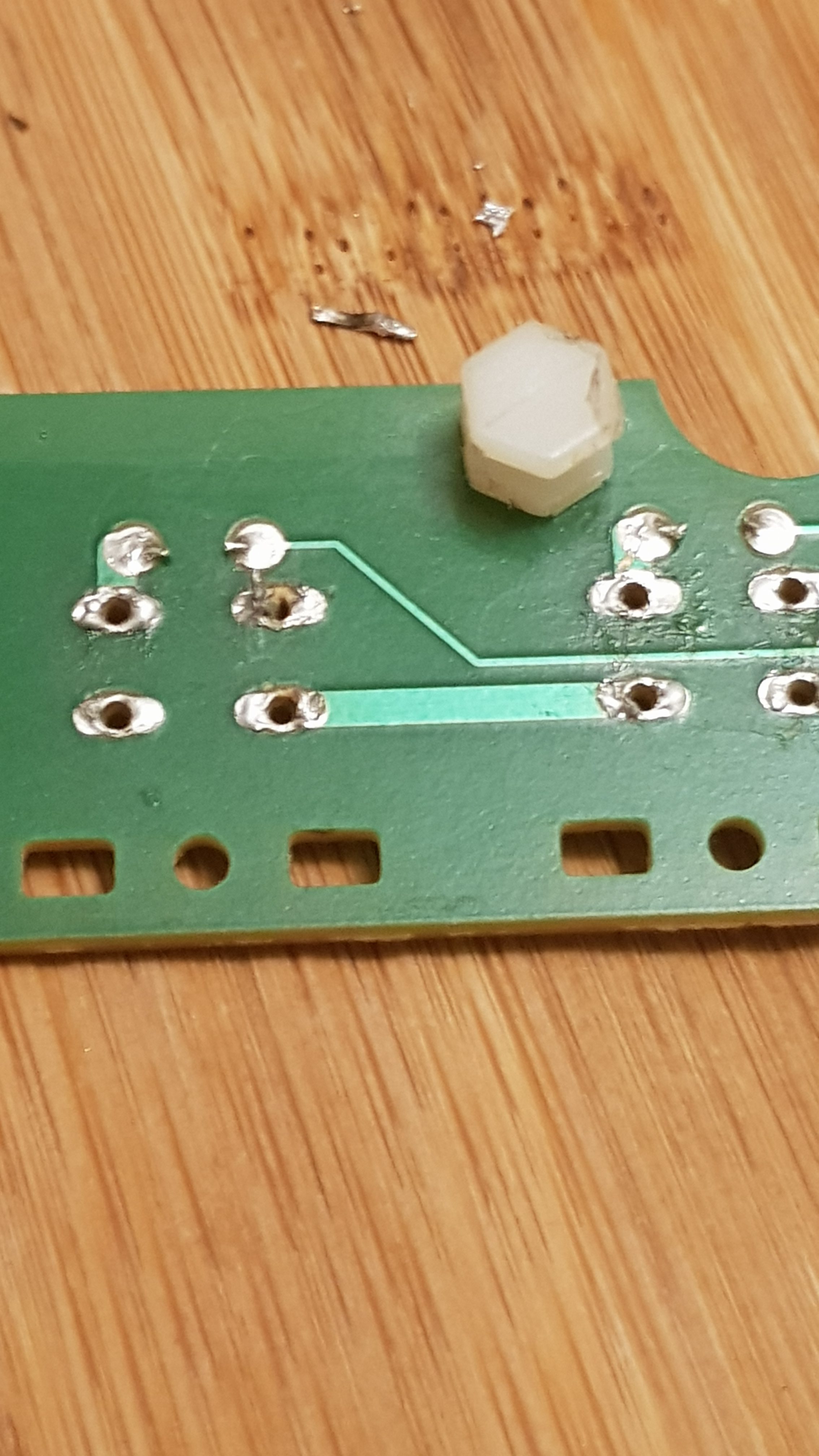
close-up of board
had made sure that the holes in the board were open,they easily slipped into their locations, and not long afterwards, were fastened in place with solder, and after making sure there were no visible electrical shorts caused by wayward solder, it was time to button everything back up and give it a whirl.
Reassemble and Test
reassembly
The answer came swiftly, because I didn’t need to reassemble the whole machine to see if these switches were working, so I popped on some black buttons I had laying around and everything worked! And now these buttons are silky smooth as well. No more mis-presses or no-presses and they will be set for another million presses. While I was there I cleaned up the pads as well which had gotten a bit grimey. I thought about replacing

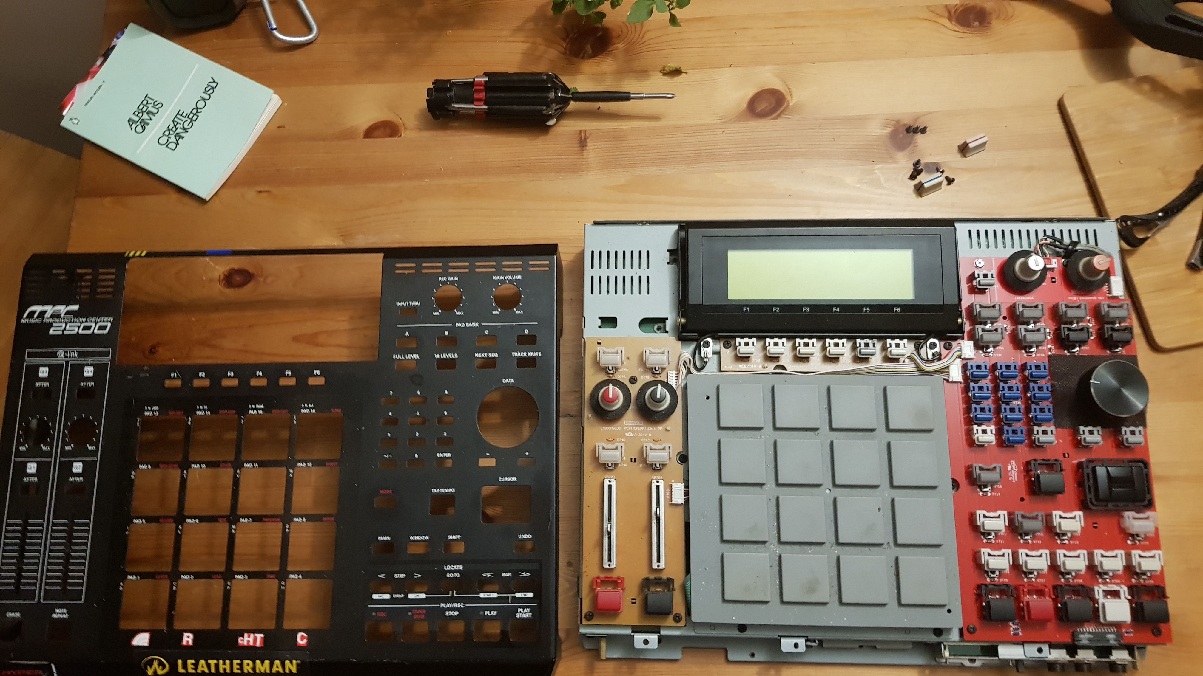
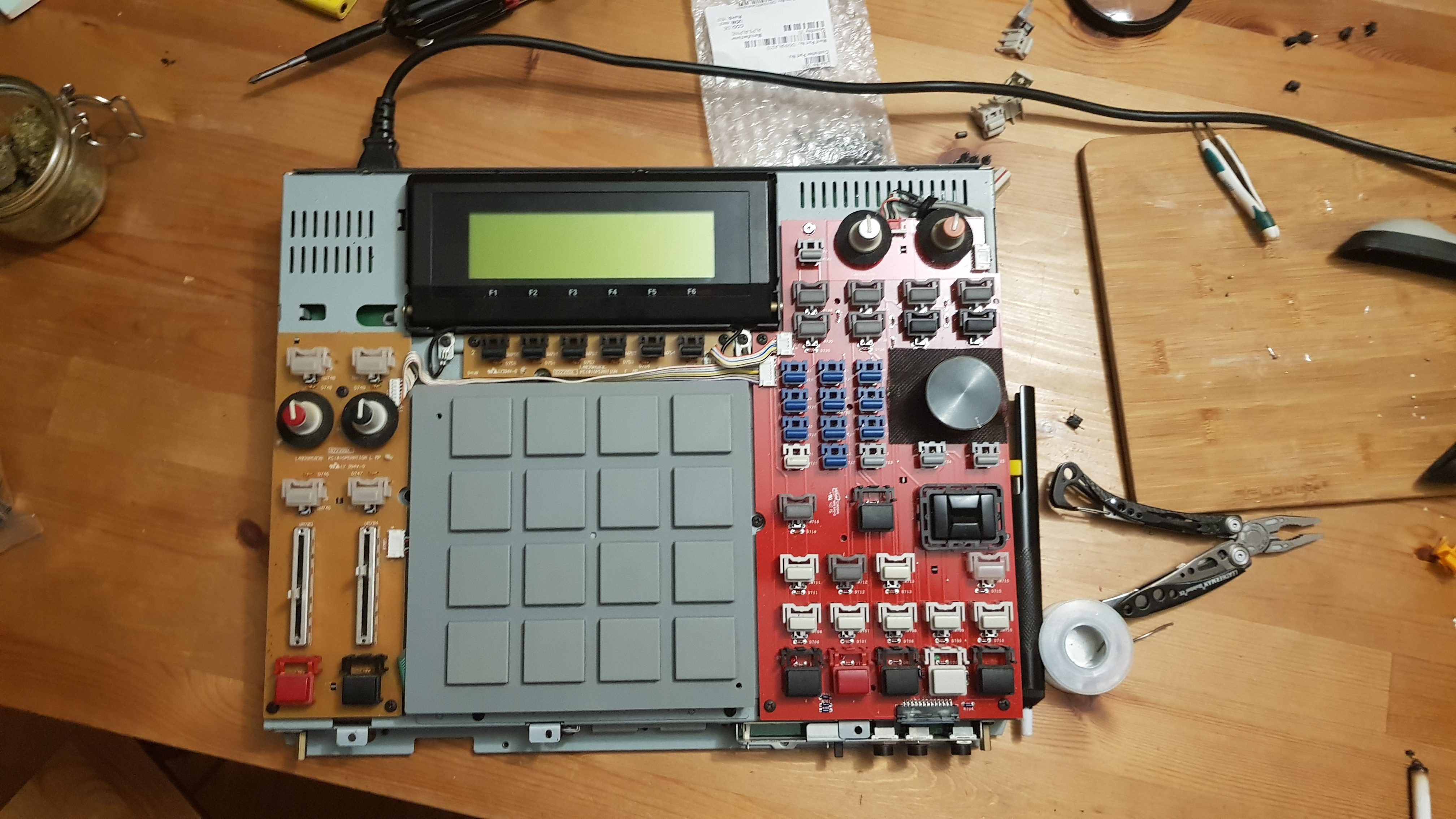
old right-side PCB
the switches on the right side of the unit, as they will probably also need replacing and actually some of them are starting to show it, I still didn’t want to do it because these buttons are not used as much in critical situations so I’d rather not risk changing them until I have to. I bought plenty of extra switches should it become necessary in the future. The board I’m using on the right side is actually an aftermarket board I bought that replaces the MPC 2500 wheel with a much better MPC 2KXL-type wheel so it should have new switches relative to the ones on the rest of the machine. As you can see in this photo of the old board on the right, all the switches use this same kind except for the transport and tap tempo buttons.
Result
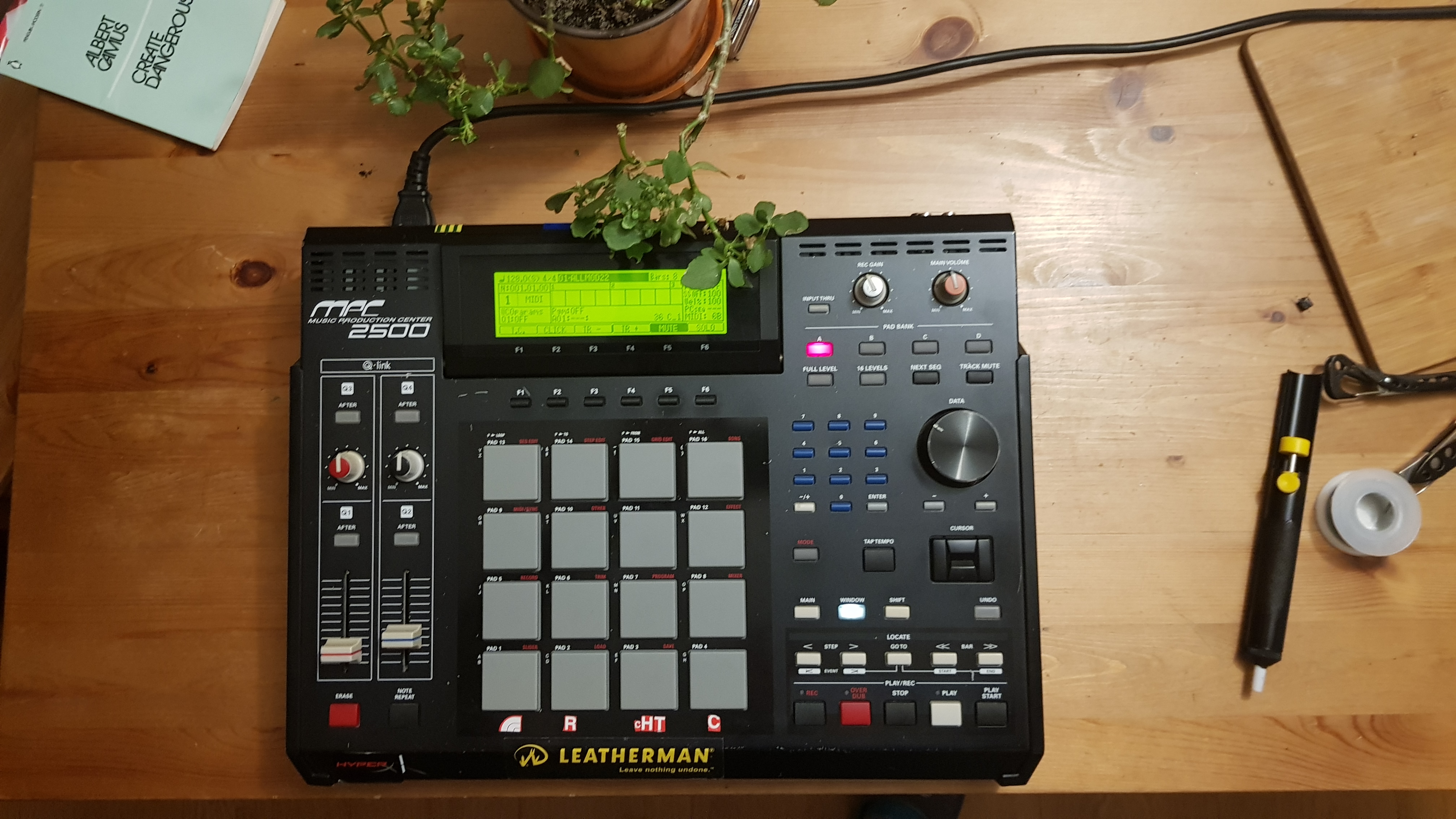
back in black
Very happy with how this turned out. I took it on myself to fix a problem and in the process saved a lot of money and will save myself lots of headaches in the future because of all the pussyfooting I had to do to avoid unintended consequences when using these switches. The soldering station was about 100zl (25$), the solder pump was 10zl (3$), and the switches themselves cost 53zl (13$) shipped for 30 of them, so for around 40$ I saved myself the hundreds or even thousands of dollars it would have cost otherwise to replace the whole machine, and is a more permanent solution than just replacing that board. I tried it out last night and it is like a completely different machine. Stoked to finally fix it, and do it myself, and I encourage anyone else out there who might want to try it to do the same!